Artificial Turf Drainage Plans: The Definitive Guide to Subsurface Engineering
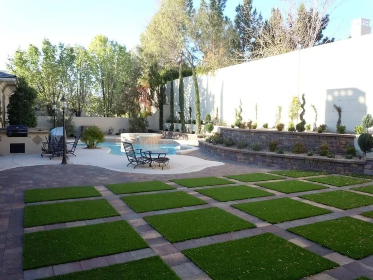
The transition from natural grass to synthetic turf is often framed as a shift toward lower maintenance and higher durability. However, this transition fundamentally alters the hydrological profile of a landscape. In a natural setting, soil porosity, root structures, and organic matter work in tandem to manage precipitation through infiltration and evapotranspiration. When these biological systems are replaced by a multi-layered synthetic assembly, the burden of water management shifts entirely to engineered physics. Without a sophisticated approach to artificial turf drainage plans, a high-performance surface can quickly degrade into a liability, characterized by sub-base instability, bacterial colonization, and surface “ponding” that renders the area unusable.
Designing for drainage in synthetic turf is not merely about moving water away from a surface; it is about managing the velocity, volume, and filtration of runoff across a non-homogeneous system. A professional-grade installation requires a deep understanding of the site’s existing topography, the geotechnical properties of the native soil, and the specific permeability ratings of the turf backing. The complexity arises from the intersection of these variables. For instance, a high-density “pet turf” requires a vastly different percolation rate than a decorative residential lawn or a high-impact athletic field.
This exploration delves into the structural and fluid dynamics that define successful installations. We will move beyond the common oversimplification that “gravel drains water” and instead examine the layered hierarchies of aggregate gradations, the role of geosynthetics in stabilization, and the long-term maintenance cycles required to keep these subterranean systems functional. This is a study of invisible infrastructure, the hidden engineering that ensures a synthetic landscape remains both aesthetically pleasing and structurally sound over a twenty-year lifecycle.
Understanding “Artificial Turf Drainage Plans”
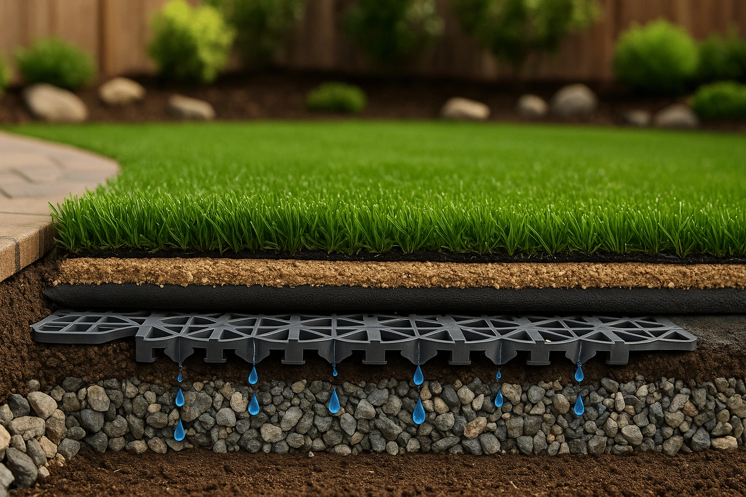
In the context of modern landscaping, artificial turf drainage plans represent the technical blueprint for a site’s moisture management strategy. These plans are frequently misunderstood as simple grading exercises. In reality, they are comprehensive hydrological models that must account for three distinct phases of water movement: vertical infiltration through the turf and infill, lateral migration through the aggregate base, and final discharge into the local watershed or municipal stormwater system.
The most common misunderstanding is the “perforated vs. permeable” debate. Standard synthetic turf is typically perforated with small holes (roughly every four inches) to allow water to pass through the backing. However, more advanced “100% permeable” backings utilize a non-perforated, woven fabric that allows water to flow through the entire surface area. A drainage plan must align the turf’s flow rate (measured in inches per hour) with the sub-base’s capacity to receive that water. If the turf drains at 30 inches per hour but the compacted base only allows for 5 inches per hour, the system will back up, leading to “floating” turf, a phenomenon where trapped air and water cause the synthetic carpet to ripple or shift.
Oversimplification risks are high when contractors apply a “one-size-fits-all” base depth. A 2-inch base of crushed stone might suffice for a desert climate with sandy soil, but the same specification in a clay-heavy region of the Pacific Northwest would be a recipe for catastrophic failure. A legitimate plan evaluates the “California Bearing Ratio” (CBR) of the native soil to determine how much structural support and, by extension, how much drainage void space is required to keep the surface level under hydraulic pressure.
Deep Contextual Background: The Shift from Permeability to Management
The history of synthetic turf drainage has evolved from “sealed” systems to “open” systems. Early generations of AstroTurf in the 1960s and 70s were often installed over asphalt or concrete. These were essentially impervious surfaces; water was managed entirely through surface runoff, directed toward perimeter drains. This led to significant heat retention and high-velocity runoff that could overwhelm local sewers.
The second generation introduced the “e-layer” (elastic layer) and the transition to crushed stone bases. This shifted the focus to vertical drainage. The goal became “attenuation”—using the stone base as a temporary reservoir that slows down the water before it hits the soil. Today, we are in a third-tier evolution where drainage plans are increasingly influenced by LID (Low Impact Development) standards. Modern systems are designed not just to move water, but to filter it. The use of antimicrobial infills and zeolites within the drainage layers reflects a growing concern for the quality of the water leaving the site, particularly in urban “heat islands” where runoff temperature and pollutant loads are strictly regulated.
Conceptual Frameworks and Mental Models
To grasp the intricacies of drainage, one must apply specific mental models that govern fluid movement in porous media.
-
The Reservoir Model: View the aggregate base (the “road base” and “finishing stone”) as a battery for water. Just as a battery stores energy, the void space between stones stores water during a peak rain event. The “void ratio,” typically 20% to 40% for clean crushed stone, determines how much rain the system can hold before the water level rises to the turf backing.
-
Darcy’s Law Application: While complex in a laboratory setting, the simplified version for drainage planning is that the flow rate is proportional to the hydraulic gradient. If you want water to move faster, you need a steeper slope or a more porous material. Understanding this helps designers realize that a perfectly flat field is a hydrological challenge, not a benefit.
-
The Filter Cake Phenomenon: This is a risk-based framework. Over time, fine particles (dust, broken-down infill, organic debris) migrate downward. If the drainage plan doesn’t account for these “fines,” they will eventually clog the interface between the stone base and the native soil, creating an impermeable layer or “filter cake” that kills the system’s efficiency.
Key Categories of Drainage Architectures
Not all artificial turf drainage plans follow the same structural logic. The choice depends on the intersection of budget, climate, and usage.
| System Type | Primary Mechanism | Best Use Case | Key Limitation |
| Punch-Hole Perforated | Vertical flow through 1/4″ holes. | Residential lawns, low-traffic areas. | Prone to clogging in high-silt environments. |
| Full-Flow Permeable | Micro-porous woven backing. | Pet turf, high-rainfall regions. | Higher material cost; requires a cleaner base stone. |
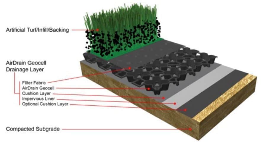
| Air-Void / Grid System | 1″ plastic grid “cells under turf. | Rooftops, balconies, ultra-high flow. | Significant cost increase; requires perimeter capture. |
| Trench & Pipe (Traditional) | Gravity-fed perforated pipes in the base. | Large athletic fields, clay soils. | Complex excavation; potential for “telegraphing” lines. |
Decision Logic for Architecture Selection
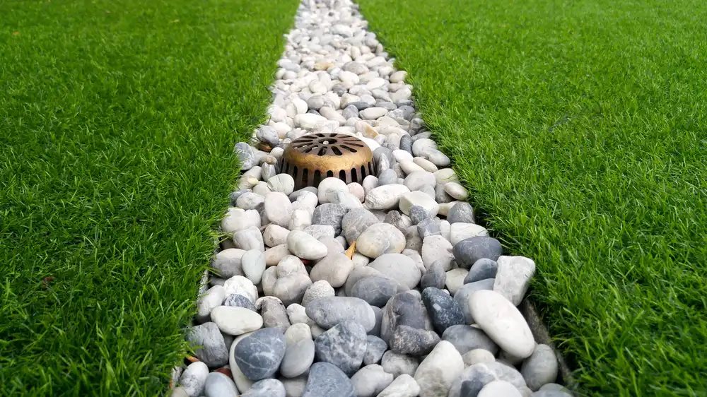
When choosing between these, the primary decider is the “Infiltration Rate” of the sub-grade. If the native soil is expansive clay, a vertical-only drainage plan will fail because the water has nowhere to go once it hits the clay. In this scenario, a “Positive Drainage” model is required, involving a sloped sub-grade (usually 1% to 2%) and a network of lateral “finger drains” that lead to a central collector. Conversely, in sandy soils, a “Dispersal” model is sufficient, where the soil itself acts as the primary drainage vehicle.
Detailed Real-World Scenarios
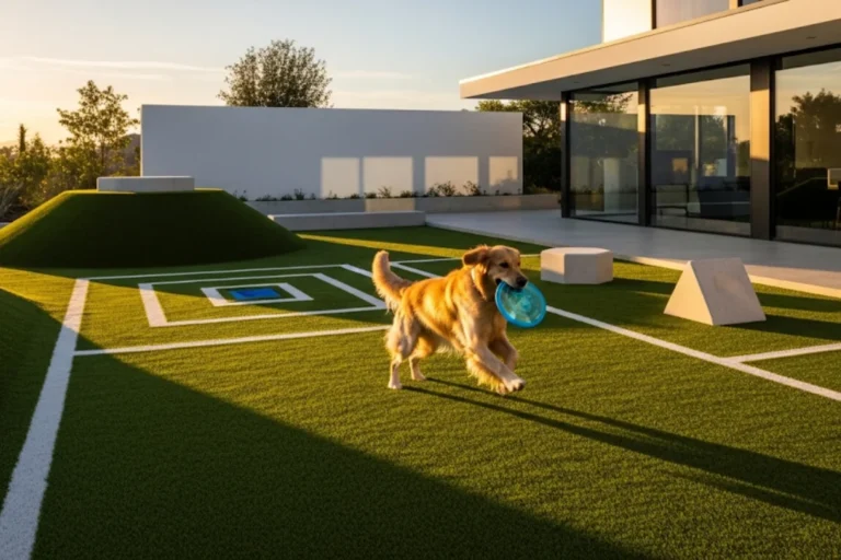
Scenario A: The Urban Pet Relief Area
Constraints: Small footprint, high nitrogen load (urine), heavy daily cleaning with water.
The Plan: A high-flow permeable backing over a “no-fines” 78-stone base. The focus here is not just volume, but “flushability.” The plan must include a slight pitch toward a floor drain or exterior landscape bed to prevent ammonia crystals from building up in the stone matrix.
Failure Mode: Using a standard road base with “fines” (dust/sand). The urine reacts with the stone dust to create a cement-like crust, trapping odors and blocking water.
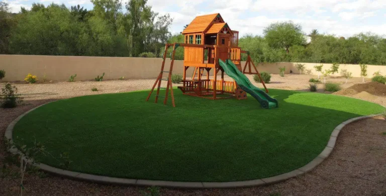
Scenario B: The Hillside Residential Play Zone
Constraints: Significant slope, potential for erosion, high velocity of surface runoff from adjacent “hardscape” (patios).
The Plan: Interceptor drains at the top of the slope to catch “sheet flow” from the patio before it reaches the turf. The turf base itself must be “benched” or stabilized with a geogrid to prevent the aggregate from migrating downhill during a saturation event.
Second-Order Effect: Without interceptor drains, the volume of water can actually lift the turf and slide it down the hill, even if the drainage plan for the turf itself is perfect.
Planning, Cost, and Resource Dynamics
The financial architecture of artificial turf drainage plans is often skewed toward the “visible” components (the grass), while the “invisible” components (the base) are where the long-term ROI is determined.
| Expense Category | Typical Range (Per Sq. Ft.) | Impact on Longevity |
| Standard Aggregate (Crushed Stone) | $1.50 – $3.00 | High – Provides the foundation and initial void space. |
| Geotextile Fabric (Stabilization) | $0.20 – $0.50 | Moderate – Prevents base sinking into sub-grade. |
| Subsurface Pipe Network | $1.00 – $4.00 | Critical in clay soils – Prevents saturation. |
| Permeable “Air-Void” Panels | $4.00 – $8.00 | High – Essential for rooftops or zero-clearance drainage. |
Indirect costs must also be considered. A poorly executed drainage plan leads to “re-leveling” costs within 3-5 years, which often exceeds the original cost of the installation because the turf must be uninstalled and re-stretched.
Tools, Strategies, and Support Systems
The execution of a drainage plan relies on specific technical interventions:
-
Laser Leveling: Ensuring the sub-grade has a consistent 1% to 2% slope toward the exit point.
-
Plate Compaction vs. Vibratory Rolling: Achieving 90%–95% compaction without crushing the stone so much that it loses its void space.
-
Non-Woven Geotextiles: Acting as a “separator” to keep the clean stone from mixing with the muddy sub-grade.
-
Perimeter “Curbing”: Concrete or composite headers that prevent water from scouring the edges of the base.
-
Clean-Out Ports: In piped systems, these allow for pressure washing the underground lines if they become clogged with silt.
-
Infill Selection: Using rounded “acrylic-coated” sand rather than jagged “raw” sand to maintain percolation pathways within the turf fibers themselves.
The Landscape of Risk and Compounding Failures
The greatest risk in artificial turf drainage plans is “Hydraulic Conductivity Mismatch.” This occurs when the layers of the system are not balanced. If the top layer (turf) is more permeable than the middle layer (sand infill), and the middle layer is more permeable than the bottom layer (compacted clay), water will pool at each interface.
Compounding risks occur during “100-year” storm events. If the drainage plan is designed for average rainfall, a massive surge can cause “liquefaction” of the base. This is where the stone becomes so saturated that it loses its structural integrity, behaving more like a liquid than a solid. This results in deep ruts and depressions that are impossible to fix without a total tear-out.
Governance, Maintenance, and Long-Term Adaptation
A drainage plan is not a “set it and forget it” system. It requires an active maintenance governance.
-
Quarterly Grooming: Power-brooming the turf to prevent infill compaction. Compacted infill is the #1 cause of surface-level drainage failure.
-
Annual Infill Replenishment: As infill washes away or breaks down, it must be replaced to protect the backing from UV rays and to maintain the vertical flow path.
-
Post-Storm Inspection: Checking perimeter drains and exit points for silt buildup.
-
Adjustment Triggers: If standing water remains 30 minutes after a rain event, this is a “trigger” that the infill has reached its saturation/clogging limit and needs deep-cleaning or replacement.
Layered Maintenance Checklist
-
[ ] Surface: Check for “matting” (fibers laying flat), which traps water.
-
[ ] Infill: Test for “crusting” (salt or silt buildup).
-
[ ] Perimeter: Clear debris from catch basins and area drains.
-
[ ] Sub-Base: Look for “dips” or “hollows” that indicate subsurface erosion.
Measurement, Tracking, and Evaluation
How do we quantify the success of artificial turf drainage plans?
-
Infiltration Rate (Leading Indicator): Using a “double-ring infiltrometer” to measure how many inches of water the system can process per hour.
-
Surface Dry-Time (Lagging Indicator): A qualitative measure of how long it takes for the turf to feel dry to the touch after a heavy rain.
-
Base Stability (Structural Signal): Using a “string line” or laser level once a year to track any settlement in the aggregate.
Documentation Examples:
-
As-Built Maps: Showing exactly where the underground pipes and “dry wells” are located.
-
Percolation Logs: Pre-installation and post-installation flow tests.
-
Sieve Analysis Reports: Documentation of the specific stone sizes used in the base.
Common Misconceptions and Oversimplifications
-
Myth: “Turf drains better than grass.”
-
Correction: Only if the subsurface is engineered correctly. Unengineered turf over clay is significantly less permeable than healthy grass.
-
-
Myth: “You need a plastic liner under the turf.”
-
Correction: This is catastrophic for drainage unless you are intentionally “harvesting” rainwater. Liners trap moisture and cause mold.
-
-
Myth: “Sand is a good base.”
-
Correction: Sand holds water via capillary action. A “crushed stone” base is vastly superior for drainage.
-
-
Myth: “Deeper gravel always means better drainage.”
-
Correction: Without an exit point (a pipe or a slope), a deep gravel bed is just a larger “bathtub” that will eventually fill up and overflow.
-
-
Myth: “The holes in the turf are enough.”
-
Correction: In heavy rain, 1/4″ holes can’t handle the volume; the entire base must be designed for lateral flow.
-
Synthesis and Strategic Judgment
The efficacy of artificial turf drainage plans lies in their invisibility. A successful plan manages the violent energy of a storm and the slow, corrosive potential of standing water without the user ever noticing. It requires a shift from “landscaping” to “civil engineering” at the residential and commercial scale.
Ultimately, the goal is “Hydrological Neutrality” creating a system where the runoff profile of the synthetic installation mimics or improves upon the natural state of the land. This requires an honest assessment of site limitations and a refusal to cut costs on the layers beneath the surface. As climates shift toward more extreme weather patterns, the ability of these synthetic landscapes to adapt to high-volume events will be the ultimate test of their design. The “best” plan is the one that accounts for the worst-case scenario, ensuring that the investment remains stable, sanitary, and functional for decades.